#include<LiquidCrystal.h>
// Pin setup: RS, EN, D4, D5, D6, D7
LiquidCrystal lcd(2, 3, 4, 5, 6, 7);
void setup() {
lcd.begin(16, 2); // Initialize 16×2 LCD
lcd.print(“Hello, World!”); // Print on first line
lcd.setCursor(0, 1); // Move to second line
lcd.print(“Arduino + LCD”);
}
void loop() {
// Nothing here for now
}
data that is the pin that goes from 0
1:30until 7 then for our
1:33connection we are going to do the following
1:35To start we are going to make the system of
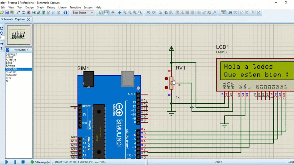
1:37connecting our screen
1:40for this and simulating that we can
1:42To change the brightness we are going to use
1:43a potentiometer
1:46we place our potentiometer
1:48and we adjust this here then we go
1:52to feed our potentiometer to
1:54current for that we go here
1:59and we choose the voltage from there we go to
2:03connect it to ground as well
2:05so we connect here and here we have
2:08our land
2:10Now how is it that we have the following
2:11connection
2:13Well, to start our ping bcs of
2:16our display is going to connect to the
2:18ground of our potentiometer, that is
2:20is to know connected to this one here
2:22our ping vdd is going to be connected to the
2:27current of our potentiometer
2:30that is, this one here
2:33and finally our ping be va
2:36connected
2:39at the output of our potentiometer
2:41So with us let’s vary
2:43the resistance of the potentiometer
2:45screen luminescence will go
2:47decreasing increasing in the simulation
2:50we can’t see this effect for effects
2:52practical from the following
2:53program we are no longer going to connect
2:57if we do not move forward under these conditions
2:58because it’s going to start to saturate
3:00a little bit the screen compared to the others
3:02systems we are controlling
3:04So what’s next then?
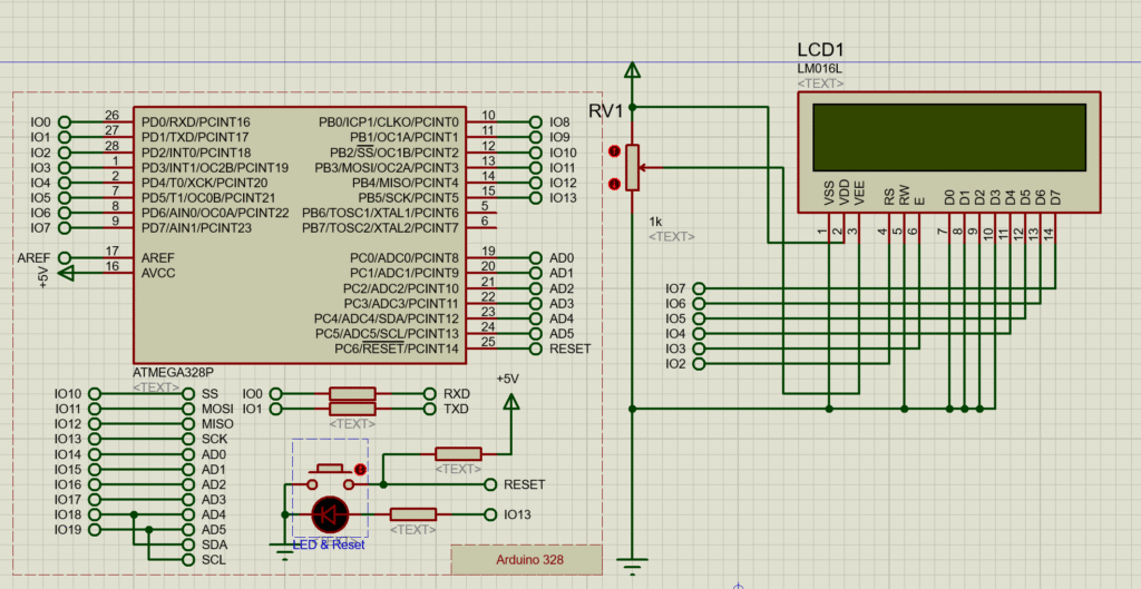
3:07depending on how we have configured
3:08our program the pins the rs pins
3:13from 4 to 5 and 16 and 17 are going to go to their
3:16respective connection as per
3:17Let’s configure it in our sketch
3:19from Arduino for our case we are going to
3:22configure rs ping to go to pin
3:25number 2
3:33to pin number 2 the ping and go to pin
3:37number 3
3:39ping 4 go to pin number 4 pin
3:44from 5 go to pin number 5
3:49I’m going to fly for the 5 pin
3:52pin 5 by pin number 5 by pin 6
3:56go to pin number 6 and pin 7 go
3:59to pin number 7 finally our ping
4:03of the reader and writing we are going to
4:05ground
4:07then with a new land
4:10we make the connection
4:16In this case we are going to move a little bit
4:18plus this
4:21to be able to make the connection
4:26and with this we have it configured
4:28our screen takes into account connections
4:30So let’s see now how it is that
4:32the script works ruin or to be able to
4:34control an LCD screen
4:39For our first program we are going to
4:40do something very simple what we are going to do
4:42to do is that our display we are going to
4:44print a greeting on both your first
4:46row as in its first second in its
4:49second row press
4:51for this is the first thing we have
4:53what to do to be able to use
4:55correctly the display in arduino
4:57what we have to do first is
4:58declare our controlling library
5:00our display this as we can
5:02do it because we can do it directly
5:04copying the name of the library that is
5:06even liquid crystal point ho go to
5:14program
5:16include library and here directly
5:19We already have our library which is the
5:21Liquid Crystal bookstore
5:24the click crystal bookstore then a
5:26once it is declared that it is what
5:27let’s do let’s declare the pins
5:30in which our LCD is connected in
5:32our case is connected the pin of
5:35reset
5:37to pin number 2 of our ordino the pin
5:39enable pin number 3 of our ordino
5:42pin 4 to number 4 pin 5 to
5:46number 5 ordered us the pin from 6 to
5:49number 6 of our ordino and the pin of 7
5:51to number 7 then this is super
5:53important because depending on the
5:55type of connection we have in our
5:56proteus circuit are going to be the
5:58respective pins that we are going to have to
6:00declare in this part but always
6:02following that order the pin r is the pin
6:05enable pin 4 pin 5 pin
6:07of 6 and the pin of 7 depending on how
6:09will be the connections we have in
6:11our program
6:13then already within our program
6:14which is the first thing we have to do
6:16to do is to declare the beginning of our
6:19LCD interface for this we use the SD
6:22and Beijing 16, that is to say we are
6:24using we are telling you boast 1
6:26that we are using an LCD screen
6:28which has 16 columns and 2 piles
6:32from there we use the command of the
6:36instruction6:36lc point click which is going to give us
6:40Performing a clean will cleanse us
6:41our LCD screen
6:44Hence the second important instruction
6:47what we have is lcd points the cursor that
6:50that is going to help us
6:51position the cursor where we want it
6:53write in our case we are
6:55putting that they write the position 0 0 is
6:59say the one that is equivalent to the column
7:00number 0 and row number 0 if
7:03We would like our text to
7:04would not appear in this for example
7:06appeared in the row in the column
7:08number 5 and in the second line
7:10we would have to put column number 5
7:13column number 4 since this one starts
7:15from zero and row number one and row
7:18number one then with the instruction
7:22From the cursor what we are going to choose is the
7:24positioning where we want it to be
7:25start our text now for the
7:28LCD print function what it will do to us
7:31It is everything that is inside that
7:33instruction will not print them on the
7:35LCD screen in the position where
7:37we choose the cursor in this case
7:40We are asking the program to
7:42on the LCD we put the word hello to
7:44all and from there it will jump to the
7:47next row corresponding to
7:50row number 1 in this case we are
7:53saying that position the cursor on the
7:55fil in column number 0 and in row
7:58number 1 to write the word that
8:02be well with a happy face
8:04So let’s see next the
8:06operation of this program the only thing
8:08what is going to happen to us then is in the
8:10row number in the first row is going to give us
8:13write the word hello everyone and in the
8:15second row is going to write us the
8:17word that they are well with the face
8:19happy
8:23if we run our program
8:25First we load it edit properties in
8:29Our case is already called LCD.
8:32or line or we load it and proceed to
8:35run what is what we are going to see
8:37time for us to run the simulation
8:39Let’s see what it actually says.
8:41Hello everyone, may you be well in
8:44In this case we can see that the
8:45Our smile is also because it is already
8:47We cover the 16 spaces that are
8:49available for LCD and if we
8:52we try to vary the contrast and
8:54varying the value of the potentiometer
8:55we can see that it does not attenuate, that is to say
8:58We cannot simulate this function in the
9:00simulator then I repeat it again to
9:03from now on to save a little
9:05space since it is going to be very saturated
9:06our image and connections we are going to
9:09stop connecting our system
9:12screen lighting which does not work
9:14enter to alter in any way which is not
9:17does not alter in any way the simulation of our
9:19problems
9:20For our second example we will
9:22control through two switches
9:24of the switching on and off of two LEDs
9:26so that when we turn off
9:29Let’s learn one of the things the screen is going to tell us
9:31to say which ones have been learned
9:32which ones are we going to pay?
9:35Next, we will show our program
9:39for our second program what is it
9:40that we are going to use, then we are going to
9:42use two switches for this al
9:45principle of our program always
9:46We have to declare the library first.
9:49of the LCD, that is, we declare to include
9:52liquid crystal dot hy again we go
9:54to declare the pins that we are going to
9:56use for our program the
9:58which ones are which ones are which ones are
10:00those who are connected to our
10:01license for this example we are going to
10:03use the same connection to say the
10:04pins 2 3 4 5 6 and 7
10:09Now then, what are we going to declare?
10:11Well first we are going to declare the
10:12integer variable that one that is going to be
10:15assigned to the kings to zero that is going to be
10:17our first switch from there we go to
10:19have declare the integer variable s2
10:21which will be assigned to our
10:23first to our ping to one that is going to
10:25be the file two where it will be
10:27connected and integer variables value
10:29one and value two which are the ones that are going to
10:31save the values of our
10:32variables
10:34then again in boise i had initial
10:36made the lcd screen 16 by 2 and although
10:39clean it and I’m going to declare our
10:43switch one of our switch 2 as
10:45inputs while the pins on the
10:47that our red LED is connected and
10:49our blue led I’m going to declare them as
10:51exits now within our bildu
10:54What are we going to do first?
10:56What we want is for it to give us the value
10:57digital switch input number
11:001 and 6 number 2 to see what
11:02state are and then through the
11:04while statement we are going to do that
11:05while the value one is identically
11:090 and the value 2 is identically 0 is
11:12say the case when the two are there
11:16off we want you to tell us then
11:20that the red LED is off is
11:23on and the blue LED is also on
11:25on
11:27and that our screen prints for us
11:29LCD, that is, position it in the first
11:32row will be the data of our LED
11:34red and in the second row will be
11:36the data of our blue
11:38and that he reads us again
11:40values that the switches are taking
11:42so that I can go out to the cool and go to
11:44the next to the next condition
11:46then for the second condition
11:48when switch number one is on
11:51on and the 6 number 2 is off
11:53We then want the LED to turn on.
11:55red and that turns off the blue LED and that
11:59Our LCD tells us that the red LED
12:01is on and the blue is off
12:04and again the values of were won
12:06our switch so that it actually
12:08verify
12:09so we can get out again
12:11our sentence well now finally
12:14when we want that while
12:18our census of our switch number 1
12:20This payment for our switches number 2
12:21is on then we want that
12:24now the red led turns off and it gives you
12:26blue turns on meaning that our
12:29LCD screen displays in the first row
12:32it turns off red and turns on blue
12:35and again not only to read the
12:37values of our variables to be able to
12:39leave the web12:39and now finally when the two
12:41are on we want them then
12:44the two scenes tell us that the two
12:45are off then let’s see
12:48continuation of the simulation of this
12:49program
12:51then with our circuit and assembly
12:53which corresponds to the same circuit as
12:55we have for example 1 but without the
12:56power supply system the two LEDs that
12:59are connected to pin number 12 to pin
13:01number 13 and that is through a
13:03resistance are connected to ground and
13:07Finally, our two switches are going to
13:09see what actually happens is then
13:11At the beginning we have our pins
13:13our switches we turn off our
13:15connected sayings, that is, it is marking
13:16that rock is off and age alone
13:19is off then what happens if
13:21we give the number one yes
13:23We disconnect it and the LED will turn on.
13:26blue and it will tell us on the display that
13:29Blue LED is on, what happens then?
13:32If we now give the LEDs to the switch and
13:35number one is on because now it’s going to
13:38the red LED will also turn on and it will
13:40tell our display that the red LED
13:42is also on
13:44So if we turn off the switch
13:48number 2 will turn off the blue LED and
13:51Our display will tell us that now
13:53he is red he is the one that is on and the
13:54blue led is off, that is, we are
13:57showing on our screen of the
13:59states that our LEDs are taking to
14:02Next we will see our third
14:03program in which we are going to show in
14:06the screen the speed of rotation of about
14:09motors from control with a
14:11potentiometer
14:15for our third program what is it
14:17What are we going to use to start with?
14:19let’s declare an integer variable
14:21called value which will serve us
14:23to
14:25the analog value it is delivering
14:27our potentiometer and there we go
14:31have the variable between also the
14:33speed which will help us to
14:34quantify the speed of our
14:36engine remember before this that the
14:38analog value that our can take
14:39potentiometer is a value that will suffer
14:411.023 while the spin speed
14:43that our engines can have is a
14:46speed ranging from 0 to 255
14:49then we are also going to define the
14:51variable enter scale which will give us
14:53help from that value to be able to do
14:56a scale in percentage of the speed
14:57of the turn the engines are taking
15:00the entire potentiometer variety which
15:02will replace the pin to 0 to make a
15:04makes it easier to name them and
15:06Finally, a counter that is the
15:08integer variable and again we return to
15:10declare our display’s library
15:12with in club
15:13liquid crystal dot hy the pins in
15:16those who are connected to our display
15:17which are again 2, 3, 4, and 5
15:20the 6th and the 7th
15:22so that’s how I’m going to be certain what it is
15:24Let’s do it, let’s start.
15:25initializing our display with the
15:28Beijing LS ruling 16.2 hence
15:32We are going to ask you to read to us that
15:34screen and with a for loop we are going to
15:36declare all the outputs we are going to
15:39occupy to control our
15:40engines
15:42with another pin we are going to declare ourselves
15:45our variable potentiometer of the
15:46heart of al have 0 as an entry
15:49So what do we have here? We’re going to
15:51declare a new function that is going to be
15:54the spin function which is going to be
15:56that will make us spin our
15:57motors with a speed at a
16:01speed related to the
16:03variable candle then an engine will go down
16:05to the right while the other goes
16:07to turn left
16:09then already within our program
16:11What we have is the following:
16:13First we want you to do our
16:15program is to read the analog value
16:17that the potentiometer is taking is
16:19say this is the value that goes from 0 to
16:211.023 then and once you read it then
16:25we have to scale it so that
16:27effectively at the time that we
16:29let’s put it inside our engine
16:31where the value it can take is from 0 to
16:34255 if that relationship is fulfilled as
16:37We do this because we can do it
16:38next if we divide 1.023
16:41between 255 the value that it gives us is a
16:45value of 4 points and so many, that is to say a
16:47factor by which we can scale this
16:49value so that 1.023 corresponds to
16:52the 255 corresponds to dividing the
16:55variable value between 4
16:58so
17:00In this way we declare the variable
17:01speed as a value between 4
17:04Now for our LCD to print for us
17:07actually the percentage of speed that
17:11This is turning then we have to
17:13to make a new scaling is to say that
17:16by the time the speed is zero then
17:18corresponds to zero percent and when
17:19the speed is 255 corresponding to 100%
17:23How do we do this? We do it
17:25division of 255 by 100 which gives us
17:29a factor of 2.55 that is to say our
17:32variable scale so that it can meet
17:33this so that I can fulfill that
17:36condition of going from 0 to 100 we have
17:37that divide the variable speed by
17:39255 from there we will call the
17:43spin function that will take the values
17:45of the variable speed
17:47then already inside our display
17:50What do we want you to do first?
17:51We want you to position yourself in line
17:54number 0 and column number 0 with the
17:55LCD statement points the cursor once
17:59that is positioned there we want that
18:02print us the text engine speed 1
18:06and that within the same line it is not
18:08print the value of the variable scale
18:10That is, for us to print the value
18:13We are no longer going to use a variable
18:14the text in quotation marks because we want
18:17which prints this value when
18:19we want to use that is not
18:21print a word or text always
18:23we have to put it in quotes
18:26This case is what will impress us when we do not
18:27tell the display by not telling the
18:31arduino that moves from column to column
18:34move ranks what is going to follow us
18:36writing in the same row
18:38That is to say, until we give a
18:41lcd the cursor again where we
18:44that we send the row or column in the
18:46that we are working everything is going to
18:48write continuously about the
18:49same row then we want that
18:52print the engine text the value of
18:55our scale variable and the sign of
18:57percentage to tell us that this is
18:58related to the percentage of rotation of
19:01our potentiometer
19:02that for our engine 1 then for
19:05our engine 2 taking advantage of our
19:07display has two rows let’s jump
19:10of row that is to say now we want that
19:11we are in column number zero and in
19:13row number one then already with the
19:16cursor positioned is the place we go
19:19to proceed to print our text
19:20Now what we want is not to be printed
19:22is the text engine speed 2
19:25then we print this ex text and
19:28At the same time we want you to print us on
19:30the same place the value of the variable
19:32scale
19:33and the percent sign
19:36So now next we are going to
19:38show how our program works
19:40in proteus
19:43and in processes we already have our system
19:46made the connections again
19:48Our display has not changed yet
19:50being the same as in the first
19:51program we only remove the connection
19:53of the brightness of the display because it is already
19:56is piling up more and more then
19:58we have our connection from our
19:59driver for the 29 3d connection
20:02our engines which are powered
20:04to a 24 volt voltage source for
20:06that the change of is more illustrative
20:08speeds in the turn we have our
20:10two engines and we have our
20:12potentiometer which will help us
20:15control the speed of this then
20:18If our program is good, what is it?
20:19that it has to show us on the screen
20:20LCD has to show us the same
20:22percentage that is registering
20:26our potentiometer in the program
20:29proteus or let’s run the simulation
20:30to see that this is indeed
20:32TRUE
20:33So here we have that they are
20:36showing a value of 38 and here we have
20:38which is showing us a value of 39
20:40here it may vary as to the
20:41division values for example here
20:44we have a value of 25 and we see that
20:46indeed the engines are running
20:49slower if we increase this
20:52value here we are at 79 as the
20:54potentiometer says it and it is not
20:56indicating that the speed of the two
20:57engines is 79 and so we can go
21:01varying the values to see that
21:02effectively agree with the value of
21:04turning the potentiometer the values of the
21:06speed that our is throwing at us
21:09display below we will see
21:11Our last example is what is the
21:14importance of displays
21:16to be able to obtain the data without the need
21:18have the serial monitor open or on
21:20our case without having to have
21:21connected our computer to the terminal
21:23that is, through the use of our
21:26sensors we will be able to obtain data from
21:28manually by displaying the value that
21:30They are taking on the displays then
21:33We are going to carry out a program in which
21:35we are going to show the values that are
21:38taking
21:39sensors the ultrasonic sensor and our
21:41sensor cn 70
21:47For our last program we are going to
21:49do we are going to show on our display
21:52the values taken by the sensor
21:54ultrasonic and our sensor
21:586
21:5990
22:01so what are we going to do
22:03First we are going to declare the pins in
22:04those that are connected ultrasonic
22:06This is the trigger pin which is the number
22:1012 and the eco pin which is number 11
22:12we are also going to declare a whole real
22:14value which will serve us for
22:16save the analog pin value to 0
22:18in which you will be connected to
22:19our reflective census once again
22:22We declare the library again
22:24our LCD on the pins it is on
22:27connected to us will be the ruin that
22:29They remain the same in the voice
22:31tube we start the lcd interface and
22:34we clear the screen and declare to
22:37trigger pin as output to the echo pin
22:40commented and pin number to 0 as
22:44entrance also already within our
22:46code the first thing we are going to ask you
22:47that reads us the value that the
22:49reflective sensor with variable length
22:53long we are going to use it to calculate
22:57the distances then in this case
23:01Since we already have the corrected factor well
23:03we are going to use only the distance
23:05with the value of t between 74 over 2
23:08for this then we are going to take since
23:11We have the data, let’s position
23:14our cursor
23:16in row number 0 column number 0 and
23:19We are going to ask you to print it for us
23:20distance in this row we are going to print
23:23the data that the elevator gives us
23:24ultrasonic then we print the
23:27distance variable which is the variable of
23:29and we print the units that are
23:31centimeters from there we position ourselves
23:35in column 0 in row number 1 and
23:38we are going to print that it is not printed
23:40text of the value that is taking a
23:42cn 1070 sensor what are the values that
23:44takes the variable value already inside
23:47Our next proteus action is
23:49see the following
23:52for our Proteus simulation
23:54we have our LCD screen connected
23:57the same way we have been
23:58We have our sensor working
24:01ultrasonic equal connected and
24:04We have previously uploaded our file
24:06ex to work properly and
24:08we have our cnc 70 sensor connected
24:11to entry 0 then what is going on
24:14to happen on our LCD screen in the
24:16first row is going to show us the
24:18distance at which our object is to
24:20by varying with the
24:21potentiometer its value on the sensor
24:24ultrasonic and will show us the
24:27distance at which they are in this case the
24:28analog that goes from 0 to 1,023 that are
24:31taking our cn 1070 sensor
24:34we proceed to run the simulation
24:39and indeed then in this case
24:41we have a distance of 199 centimeters
24:44and we vary the value of the
24:46potentiometer we see that it actually works
24:49changing in this case we have 300 and if
24:51We are going down, we are going to reach values
24:53increasingly lower
24:55for the case of our reflective sensor
24:57Let’s see that it is also true
24:59fulfills as we go
25:01raising the value the value that is
25:03They deliver analogue, it will go down
25:05remember that for this example when
25:08We have a distance here that goes from two to
25:10four millimeters corresponds to white
25:12and seven to ten corresponds to black
25:14then we can go down
25:16to see that this is indeed the case
25:18analog value is changing and going away
25:20showing on our display