
1. Wiring of Main (Power) Terminals ⚡
- Input Power: Connect 3-phase lines to L1/R, L2/S, L3/T. For single-phase, use L1/L and L2/N.
- Motor Output: Connect U, V, W to the motor. Swap two wires if rotation is incorrect.
- Grounding: Use G terminals for chassis and motor ground. Essential for safety and noise suppression.
- For motors >50 m away, use an output filter to reduce leakage currents.
2. Control Circuit & Command Inputs
a) Power Supply
- P(+)/N(–): DC 24V input for the control board or brake chopper connections.
b) Digital Inputs
- X1–X5, FWD, REV: Digital inputs configured via function codes.
- Default mode: PNP/source; change using switch SW1.
- Connect to CM for return signal.
- Use EN1/EN2 terminals to enable external control.
c) Analog Inputs
- Terminals 11, 12, 13 used for potentiometers or 0–10 V control.
- Set F01 = 1 to use analog mode; H30 = 0 for analog control over Modbus.
d) Relay Outputs
- 30A–30C: Default function is fault output; configurable via E27.
e) Transistor Outputs
- Y1, Y2, Y5, etc., used for external device control (brakes, alarms).
3. Brake Resistor and DC Link
- Use B1/B2 or P(+)/DB for dynamic braking.
- Required for heavy or regenerative loads.
- Screened cable must be grounded at both ends.
4. Programming Key Parameters
- F00: Parameter lock
- F01: Speed reference (0 = keypad, 1 = analog, 4 = internal pot)
- F02: Run control (0 = keypad, 1 = terminal)
- F03–F08: Max frequency, base freq, accel/decel time
- F11: Rated current
- F15/F16: Frequency upper/lower limits
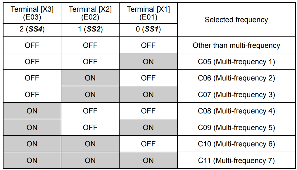
Multi-Step Speed
- Assign X1–X3 to E01–E03
- Set speeds C05–C09
5. Modbus RS‑485 Communication
- Set H30 = 3 or 8 depending on control mode.
- Set Y01–Y10 for slave address, baud rate, parity, etc.
- Use Hex 705 for frequency, Hex 706 for run/stop control.
6. Example Wiring Schematics
Basic Start/Stop
- Wire X1 to start, CM as return. Set F02 = 1.
Multi-Step Speed
- Use X1–X3 to select preset speeds via C05–C07.
Hybrid Modbus + Digital
- Use H30 = 8 for auto switching between Modbus and terminals.
7. Best Practices and Safety
- Use ferrules on all control wires.
- Separate power and control lines.
- Shielded cable for analog; ground shield at one end only.
8. Troubleshooting
- Reverse motor: swap U/V/W or change logic.
- Inputs not responding: verify PNP/NPN logic and assignment.